
Diesel Injector Installation Guide — Complete Step-by-Step with Torque Specs and Best Practices
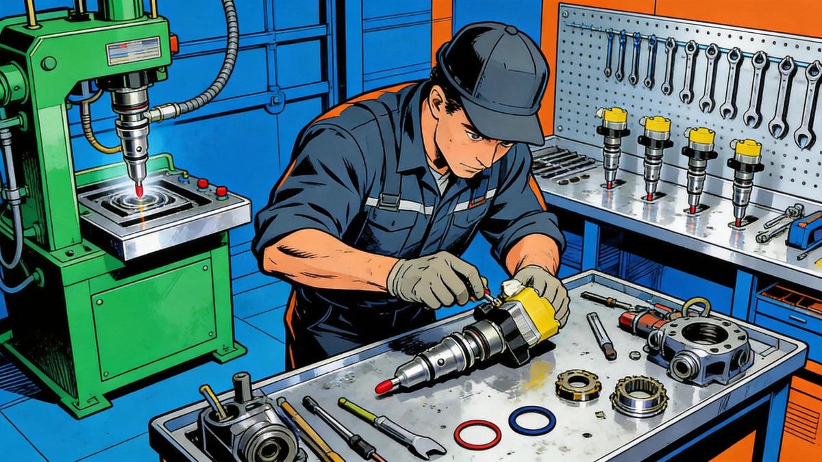
Installing a diesel fuel injector correctly is just as important as choosing the right one. A poorly installed injector — even a brand-new one — can cause leaks, misfires, poor fuel economy, and even catastrophic engine damage. In the image above, a diesel injection technician works at a well-organized workbench surrounded by tools, test equipment, and injector components — the kind of professional setup that ensures every injector goes in right. This guide covers the complete diesel injector installation process, from preparation through final leak testing, with torque specifications and best practices for the most common injector types including Bosch common rail injectors, Denso HP3/HP4 injectors, Delphi injectors, CAT injectors, and Cummins XPI injectors.
Before You Begin: Preparation Checklist
Proper preparation prevents installation problems. Before you touch a single bolt, make sure you have everything you need:
Tools Required
- Torque wrench — Inch-pound range (0–250 in-lb) for small fasteners; foot-pound range (0–150 ft-lb) for hold-down bolts. Both must be recently calibrated
- Deep socket set — 12-point sockets for injector hold-down bolts; 6-point sockets for fuel line fittings
- Combination wrenches — Metric sizes for fuel line nuts (typically 17mm, 19mm, 22mm for high-pressure lines)
- O-ring pick set — Plastic or brass picks to avoid scratching sealing surfaces
- Digital calipers — For measuring copper washer thickness and injector protrusion height
- Mirror and flashlight — For inspecting injector bores and sealing surfaces
- Compressed air — For cleaning injector bores before installation
- Vacuum pump — For priming the fuel system after installation
- Multimeter — For verifying injector electrical connections after installation
Supplies Needed
- New copper washers / sealing gaskets — Manufacturer-specific thickness and material. Never reuse old copper washers
- New O-ring kit — Upper and lower O-rings for each injector, specific to the injector model
- Anti-seize compound — Copper-based for injector hold-down bolt threads
- Clean diesel fuel — For lubricating O-rings and fittings during installation
- Lint-free shop towels — For cleaning components without leaving debris
- Thread locker — Medium strength (Loctite 242) for specific applications as specified by the manufacturer
Step 1: Prepare the Engine
The engine must be properly prepared before any injector installation work begins. Contamination entering the injector bore is one of the most common causes of premature injector failure.
- Disconnect the battery — Remove the negative terminal on all batteries. Modern diesel engines have multiple ECUs and modules that can be damaged by accidental shorts
- Relieve fuel system pressure — Follow the manufacturer’s pressure relief procedure. Common rail systems can hold 2,000+ bar of residual pressure. Refer to the system pressure relief instructions in your service manual
- Clean the area around each injector — Use compressed air and a shop vacuum to remove all debris from the cylinder head area around each injector. Any particle that falls into the injector bore will score the precision surfaces or damage the new injector
- Remove the valve cover / rocker assembly — As required for access to the injectors. On overhead cam engines, the camshaft may need to be removed
Step 2: Remove the Old Injectors
Careful removal of old injectors sets the stage for a successful installation. Rushing this step can damage the cylinder head and create problems that affect the new injectors.
- Disconnect fuel lines — Loosen high-pressure fuel line nuts at both ends (injector and rail). Use two wrenches: one to hold the fitting, one to turn the nut. This prevents twisting the fuel line
- Remove the injector hold-down bolt — Use the correct socket. Loosen progressively — don’t impact it off. The hold-down bolt can be torqued to 20–40 Nm depending on the engine
- Extract the injector — If the injector is stuck due to carbon buildup, use a slide hammer or injector puller tool. Never pry against the injector body with a screwdriver or bar — this damages the cylinder head and the injector bore
- Remove and discard the old copper washer — It will be crushed and work-hardened. Never attempt to re-use it
- Clean the injector bore — Use a bronze brush and solvent to remove carbon deposits from the bore wall. Clean the copper washer sealing surface at the bottom of the bore. Remove all debris with compressed air and a vacuum
Step 3: Inspect the Injector Bore
Before installing new injectors, carefully inspect each bore in the cylinder head. A damaged bore will cause the new injector to leak or mis-seat.
| What to Check | Acceptable Condition | Unacceptable / Action Required |
|---|---|---|
| Bore wall surface | Smooth, clean, free of carbon deposits | Scratches or gouges → cylinder head repair or replacement required |
| Copper washer seat surface | Clean, smooth, flat metallic surface | Pitting or erosion → may require machining of the seat surface |
| Bore diameter | Within manufacturer tolerance for the injector model | Oval or oversized bore → cylinder head replacement |
| Fuel return port | Clear, no blockage | Blocked → clean with solvent and compressed air |
| Hold-down bolt threads | Clean, undamaged, no galling | Damaged threads → helicoil repair or cylinder head replacement |
| High-pressure fuel port | Clean, no debris, no burrs | Debris or burrs → clean with solvent and compressed air |
Step 4: Prepare the New Injectors
New injectors come from the manufacturer with protective caps and packaging. Proper preparation before installation is critical.
- Remove the injector from its packaging — Keep the protective caps in place until the moment of installation
- Record IMA codes — For Bosch common rail injectors, record the IMA (Injector Manufacturing Accuracy) code printed on each injector. This code must be programmed into the ECU for proper fuel metering. Record the injector serial number and which cylinder it will be installed in
- Measure injector protrusion — On engines where injector height above the cylinder head is critical (such as many Cummins and Detroit Diesel applications), measure and record the injector protrusion height. This ensures the injector is seated to the correct depth
- Verify the copper washer thickness — New injectors may come with copper washers pre-installed, or you may need to select the correct thickness. Measure the old washer thickness and compare to the new one. Some applications require different washer thicknesses based on protrusion measurements
Step 5: Install the New Injectors
This is the core of the installation process. Follow each sub-step carefully.
5.1 Install the Copper Washer
- Place the new copper washer on the injector nozzle (if not pre-installed)
- Apply a thin film of clean diesel fuel to the washer to help it seat
- Ensure the washer is square on the injector — not tilted or crooked
5.2 Install and Lubricate O-rings
- Install the lower O-ring on the injector body (the one that seals the injector to the bore)
- Install the upper O-ring on the injector body
- Lubricate both O-rings with clean diesel fuel — never install a dry O-ring
- Ensure O-rings are seated in their grooves and not twisted
5.3 Insert the Injector
- Remove the protective cap from the injector nozzle
- Guide the injector into the bore by hand — never force it. If resistance is felt, remove the injector and check that the O-rings are properly seated and lubricated
- Seat the injector fully using gentle hand pressure. The copper washer should make contact with the bore seat
5.4 Install the Hold-Down Bolt
- Apply a small amount of copper anti-seize to the hold-down bolt threads (check manufacturer specification — some bolts call for thread locker instead)
- Install the hold-down bolt and tighten by hand until snug
- Torque the hold-down bolt to the manufacturer’s specification in stages. A typical torque sequence is: first stage at 50% of final torque, second stage at 75%, final stage at 100%
- Use a cross-sequence pattern if multiple bolts hold the same injector
5.5 Connect Fuel Lines
- Install the high-pressure fuel line nut to the injector
- Hand-tighten until the nut seats on the fuel line flare
- Torque the fuel line nut to manufacturer specification — typically 20–35 Nm for common rail systems
- Install the fuel return line connection
Step 6: Torque Specifications Reference
The following table provides reference torque specifications for common injector types. Always verify against the manufacturer’s service manual for your specific engine model.
| Injector Type / Engine | Hold-Down Bolt | HP Fuel Line Nut | Nozzle Nut | Notes |
|---|---|---|---|---|
| Bosch CRIN (common rail injector) | 22–28 Nm | 25–30 Nm | 60–80 Nm | Use new copper washer each time |
| Denso HP3 / HP4 | 20–25 Nm | 25–35 Nm | 60–70 Nm | IMA code programming required |
| Delphi F2P / F2E | 25–30 Nm | 22–28 Nm | 50–65 Nm | F2E requires special installation tool |
| Cummins XPI (ISX, ISB) | 30–40 Nm | 25–30 Nm | — | Protrusion height must be verified |
| CAT common rail (C7, C9, C13, C15) | 25–35 Nm | 30–35 Nm | 70–85 Nm | New injector sleeve may be required |
| Detroit Diesel DD13/DD15/DD16 | 35–45 Nm | 25–30 Nm | — | Requires specific injector height tool |
| Volvo / Mack MP7 / MP8 | 22–28 Nm | 28–35 Nm | 60–75 Nm | Injector sleeve O-rings must be replaced |
Note: These are reference values only. Always consult the manufacturer’s service manual for your specific engine application before torquing any component.
Step 7: Electrical Connections
Modern common rail injectors require proper electrical connections for the solenoid or piezo actuator.
- Verify connector cleanliness — Inspect the injector electrical connector for any debris, corrosion, or damage. Clean with electrical contact cleaner if needed
- Connect the injector harness — Push the connector firmly until it clicks or locks. Ensure the locking tab fully engages
- Check solenoid resistance — Using a digital multimeter, measure the resistance across the injector pins. Typical resistance for solenoid injectors is 0.3–0.7 Ω. Piezo injectors will show capacitance in the 1.5–3.0 µF range. Compare against manufacturer specifications
- Route the harness securely — Ensure the injector harness is not touching any hot surfaces (exhaust manifold, turbocharger) and is secured with OEM clips or zip ties
Step 8: Prime the Fuel System
After all injectors are installed and torqued, the fuel system must be primed before attempting to start the engine.
- Install the valve cover — With all new gaskets and seals
- Reconnect the battery
- Prime the fuel system — Use the hand primer pump on the fuel filter housing (if equipped) or a vacuum pump connected to the fuel return line. Pump until fuel flows freely and no air bubbles are visible in the clear return line
- Crank the engine — Disable the injectors (or remove the fuel pump fuse) and crank the engine for 10–15 seconds to build rail pressure. Re-enable injectors and start the engine. It may take 2–3 cranking cycles to fully purge air from the high-pressure lines
Step 9: Post-Installation Testing
After the engine is running, perform the following checks to confirm the installation was successful.
Leak Check
Inspect all fuel line connections, injector O-ring seals, and the area around each injector for fuel leaks. Use a mirror and flashlight to see hard-to-reach areas. Any fuel leak must be addressed immediately — fuel system leaks create fire hazards and allow air intrusion into the fuel system. Common leak locations include:
- High-pressure fuel line nuts at the injector connection
- The injector bore seal (lower O-ring) — indicated by fuel weeping down the outside of the injector
- The copper washer seal — indicated by combustion gas escaping past the injector
- Fuel return line connections at the top of the injector
Running Test
- Listen for abnormal noise — Injectors that are not properly seated or torqued may produce a tapping or knocking sound
- Check engine smoothness — Rough idle or misfiring indicates an installation or injector issue. Use a scan tool to check for cylinder balance faults
- Verify fuel pressure — Check rail pressure at idle and under load. Low rail pressure may indicate a fuel supply or injector leak issue
- Check for diagnostic trouble codes (DTCs) — Scan for any fault codes related to injectors, fuel pressure, or cylinder misfires
- Re-torque if required — Some manufacturers specify re-torquing the injector hold-down bolts after the first thermal cycle (warm up then cool down). Check the service manual
Common Installation Mistakes
| # | Mistake | Consequence | Prevention |
|---|---|---|---|
| 1 | Reusing old copper washers | Combustion gas leakage, injector overheating, power loss | Always install new copper washers with every injector replacement |
| 2 | Incorrect hold-down bolt torque | Under-torque = injector movement, sealing failure; Over-torque = thread damage, bore distortion | Use a calibrated torque wrench and follow the spec |
| 3 | Dry O-ring installation | O-ring rolls, twists, splits during installation | Lubricate every O-ring with clean diesel fuel |
| 4 | Contamination entering the injector bore | Abrasive wear, injector sticking, premature failure | Clean the area thoroughly before removing old injectors |
| 5 | Not recording IMA codes | ECU cannot correct fueling per injector; poor fuel economy, rough running | Record all IMA codes before installation. Program them into the ECU |
| 6 | Twisting high-pressure fuel lines | Fuel line stress, eventual cracking and failure | Use two wrenches when tightening fuel line nuts |
| 7 | Mixing up injector positions | Cylinders get unmatched injectors; ECU correction values are wrong | Label each injector with its intended cylinder position |
| 8 | Skipping the fuel system prime | Extended cranking, starter damage, ECU confusion from air in the system | Always prime the fuel system before the first start attempt |
| 9 | Ignoring post-installation leaks | Fuel leaks create fire hazards; air intrusion causes hard starting | Perform a thorough leak check after the first start and after the first test drive |
| 10 | Not reprogramming the ECU | Injector correction values from old injectors applied to new ones | Use a scan tool to program new IMA codes or reset injector correction values |
Special Considerations by Injector Type
Bosch Common Rail Injectors
Bosch CRIN (Common Rail Injector) injectors require IMA code programming after installation. The IMA code is a 16-character alphanumeric code printed on the injector body that tells the ECU the exact flow characteristics of that individual injector. Without this programming, the ECU applies generic correction values and cylinder-to-cylinder balance will be compromised. Some Bosch injectors also require that the injector hold-down bolt is replaced (not re-used) — it’s a torque-to-yield bolt that stretches during installation.
Denso HP3 / HP4 Injectors
Denso injectors use a similar IMA code system. The QR code printed on the injector contains the flow correction data. Use a Denso-specific scan tool or compatible aftermarket tool to read and program these codes. Denso injectors are particularly sensitive to copper washer thickness — always verify the washer depth before installation.
Delphi F2P / F2E Injectors
Delphi injectors use a unique fastening system. The F2E injector requires a special tensioning tool that compresses the injector to a specific height before tightening the clamp. Do not attempt to install Delphi injectors without this tool. The installation sequence is: place injector, compress with tensioning tool, tighten clamp bolt to spec, release tensioning tool.
Cummins XPI Injectors
Cummins XPI injectors used in ISX and ISB engines require careful protrusion height measurement. Each injector must be installed with a copper washer thickness that brings the injector to a specific protrusion height above the cylinder head surface. Use a protrusion gauge tool — the measurement tolerance is typically ±0.05mm.
CAT Common Rail Injectors
CAT injectors (C7, C9, C13, C15) use an injector sleeve (sometimes called a fuel injection tube) that fits between the cylinder head and the injector. This sleeve must be in good condition and its O-rings must be replaced whenever the injector is removed. CAT injectors also require that the high-pressure fuel connection be torqued to a specific angle (torque + angle method) rather than a straight torque value.
Post-Installation ECU Programming
Many modern diesel engines require ECU programming after injector installation. Here’s a summary of what’s typically needed:
| Injector Type | Programming Required? | What to Program | Tool Required |
|---|---|---|---|
| Bosch CRIN | ✅ Yes | IMA code per injector | Dealer-level scan tool |
| Denso HP3/HP4 | ✅ Yes | IMV code / QR code data | Denso-specific scan tool |
| Delphi F2P/F2E | ⚠️ Sometimes | Injector flow correction codes | Delphi scan tool or compatible aftermarket |
| Cummins XPI | ✅ Yes | Injector serial numbers and flow codes | INLINE 6 or Cummins INSITE |
| CAT common rail | ✅ Yes | Injector trim codes | CAT ET tool |
| Detroit Diesel | ✅ Yes | Injector calibration codes | Detroit Diagnostic Link (DDL) |
| Volvo/Mack | ✅ Yes | Injector compensation codes | Premium Tech Tool (PTT) or V-MAC |
Conclusion
Proper diesel injector installation is a precise process that directly determines the performance, efficiency, and reliability of your engine. The key takeaways: always use new copper washers and O-rings, torque every fastener to manufacturer specification with a calibrated wrench, keep the work area and injector bores surgically clean, and never skip ECU programming for the injector compensation codes. A correctly installed injector will provide hundreds of thousands of miles of reliable service. A rushed or careless installation can destroy a perfectly good injector in minutes. The time invested in careful preparation, proper tools, and correct procedures pays back many times over in engine reliability and performance.
Need high-quality Bosch injectors, Denso injectors, or CAT injectors for your next installation? Visit JSPartsonline for OEM and high-quality aftermarket options with fast shipping.




JSPartsonline:
Focus on injectors for 12 years,We sell high-quality fuel injectors at competitive prices.
Copyright 2025 © YUN·X . All right reserved.
