
Fuel Injection Pump Plunger and Barrel Assembly: Complete Technical Overview
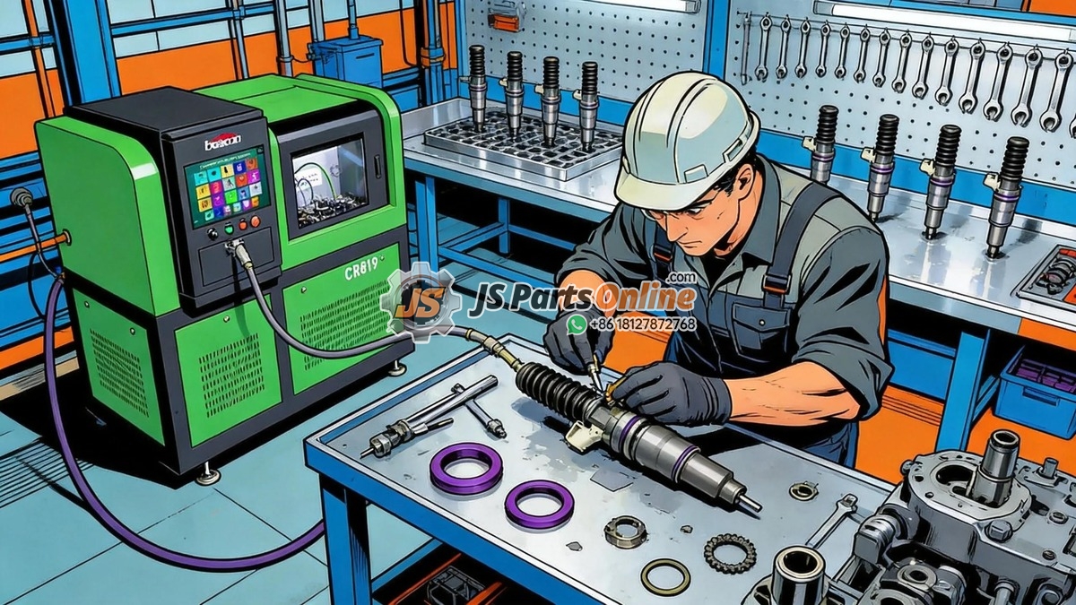
The fuel injection pump plunger and barrel assembly is the heart of every mechanical and unit-injector diesel fuel system. This precision-machined pair converts fuel pump camshaft rotation into the extremely high injection pressures—up to 30,000 PSI in modern systems—required for proper diesel combustion. Understanding how plunger and barrel assemblies work, why they fail, and how to select quality replacements is essential knowledge for anyone maintaining heavy-duty diesel engines.
1. How the Plunger and Barrel Assembly Works
At its core, the plunger and barrel assembly operates on a simple principle: a precision-ground plunger reciprocates inside a matched barrel, pressurizing a metered volume of fuel to injection pressure. The plunger clearance inside the barrel is extraordinarily tight—typically 2 to 5 microns (0.00008 to 0.0002 inches). This clearance is what allows the plunger to pressurize fuel without significant leakage while still being able to move freely.
| Phase | Plunger Position | What Happens | Critical Factor |
|---|---|---|---|
| 1. Fill | Bottom of stroke | Fuel enters barrel through inlet port; plunger descends creating volume | Fuel supply pressure must exceed barrel inlet restriction |
| 2. Spill Cutoff | Moving upward, closes inlet port | Plunger rises past inlet port; fuel trapped above plunger; pressure begins building | Helix or spill groove alignment determines injection timing and quantity |
| 3. Injection | Mid-stroke, maximum pressure | Fuel pressurized to 15,000-30,000 PSI; delivery valve opens; fuel flows to injector nozzle | Plunger-to-barrel seal must maintain pressure without excessive leakage |
| 4. Spill/End of Injection | Top of stroke, helix uncovers spill port | Helix or spill groove aligns with spill port; pressure drops instantly; injection ends | Sharp cutoff prevents secondary injection and nozzle dribble |
The helix (slanted groove) machined into the plunger is the key to fuel metering. Rotating the plunger changes the effective stroke—the distance the plunger travels between port closing and spill port opening. At idle, the effective stroke might be only 1 to 2 mm. At full load, it can be 8 to 10 mm. This rotation is controlled by the engine governor or electronic control rack.
2. Plunger and Barrel Tolerances: Why Matching Matters
Plunger and barrel assemblies are manufactured as matched pairs and must never be separated or mixed between assemblies. The manufacturing tolerances are among the tightest in all of mechanical engineering:
| Parameter | Typical Specification | Human Hair Comparison | What Happens If Out of Spec |
|---|---|---|---|
| Plunger-to-barrel clearance | 2-5 microns (0.00008-0.0002 in) | Human hair is 70 microns | Too tight: plunger seizes. Too loose: fuel leaks, low injection pressure |
| Plunger diameter tolerance | +/- 0.5 micron | 1/140th of a human hair | Incorrect clearances; plunger either jams or leaks |
| Barrel bore roundness | Within 0.5 micron | Near-perfect cylinder | Uneven wear; premature leakage path development |
| Plunger surface finish | Ra 0.05 micron or better | Mirror finish | Rough surface accelerates barrel wear; debris embeds in surface |
| Helix angle tolerance | +/- 0.1 degree | Affects injection timing precision | Cylinder-to-cylinder fueling variation; unbalanced engine |
This is why genuine or OEM-quality replacement plunger and barrel assemblies cost what they do. The manufacturing precision required is extraordinary, and attempting to use worn or mismatched components is a guaranteed path to engine damage.
3. Common Plunger and Barrel Failure Modes
| Failure Mode | Appearance | Root Cause | Prevention |
|---|---|---|---|
| Scoring / Scuffing | Vertical scratches on plunger and barrel bore | Fuel contamination—dirt, sand, or metal particles in fuel | Maintain fuel filtration to 2-5 micron absolute; replace filters on schedule |
| Seizure | Plunger locked in barrel; discoloration from heat | Water in fuel or fuel starvation causing inadequate lubrication | Drain water separators daily; never run injection pump dry |
| Erosion / Cavitation | Pitting on plunger tip or helix edge | Water in fuel; cavitation from air entrainment; poor fuel quality | Use fuel conditioners; maintain fuel system integrity to prevent air ingress |
| Wear (normal) | Gradual increase in clearance; loss of injection pressure | Normal sliding wear over 15,000-30,000 hours of operation | Replace at manufacturer-recommended intervals; monitor engine performance trends |
| Fatigue Cracking | Circumferential crack near plunger base or spring seat | Overloading from excessive injection pressure or spring resonance | Use OEM-spec springs; do not shim springs beyond specification |
4. Symptoms of Worn or Failing Plunger and Barrel Assemblies
- Hard starting, especially when hot: Worn plungers cannot generate sufficient injection pressure at cranking speeds. The engine cranks but requires extended cranking time or ether assistance.
- Loss of power under load: As plunger-to-barrel clearance increases, fuel leaks past the plunger during the injection stroke, reducing the volume and pressure of fuel delivered to the injector nozzle.
- Increased fuel consumption: The engine compensates for reduced per-stroke delivery by demanding more rack travel or longer electronic pulse width, burning more fuel for the same power output.
- White or black smoke: Low injection pressure produces poor atomization—white smoke (unburned fuel) or black smoke (incomplete combustion).
- Uneven idle or cylinder imbalance: Individual plunger wear rates vary, causing cylinder-to-cylinder fueling differences that manifest as rough idle.
5. CAT Engine Plunger and Barrel Applications
Different CAT engine families use different plunger and barrel designs. Selecting the correct replacement requires matching the engine serial number prefix:
- CAT 3406B/C Mechanical Injection Pump: Uses individual plunger and barrel assemblies inside the fuel injection pump housing. Common part numbers include 1W-6539, 4P-9827, and 7W-0561.
- CAT 3304/3306 Mechanical: Inline pump with separate plunger-barrel pairs for each cylinder. Part numbers include 7N-1185 and 6N-7527.
- CAT MEUI (C15/C18 ACERT): Unit injector system where each injector contains its own plunger and barrel. The plunger is driven by the engine camshaft through a rocker arm.
- CAT HEUI (3406E, C7, C10, C12): Does not use a traditional plunger and barrel in the injector. Instead, high-pressure engine oil drives an intensifier piston. However, the high-pressure oil pump contains plunger assemblies.
6. Selecting Quality Replacement Plunger and Barrel Assemblies
When replacing plunger and barrel assemblies, quality is non-negotiable. The consequences of a substandard plunger-barrel pair include:
- Premature wear requiring another replacement within 1,000-2,000 hours
- Low injection pressure causing poor combustion and engine damage over time
- Plunger seizure that can destroy the injection pump camshaft and housing
- Fuel dilution of engine oil from excessive plunger leakage
Always look for OEM-specification components with documented quality control, including individual clearance measurements and surface finish certifications. Reputable aftermarket suppliers provide this documentation with every plunger and barrel set.
Conclusion
The plunger and barrel assembly is a marvel of precision engineering that operates reliably for tens of thousands of hours when protected by clean fuel and proper maintenance. When replacement is necessary, the quality of the replacement component directly determines the longevity and performance of the entire fuel injection system. Choose OEM-specification plunger and barrel assemblies from suppliers who document their quality control—your engine depends on clearances measured in millionths of an inch.
Browse our complete selection of CAT fuel injection pump plunger and barrel assemblies for 3406, 3304, 3306, and other CAT engine models. Every plunger and barrel assembly ships with individual inspection certification. Contact our technical team for help matching the correct plunger assembly to your engine serial number.





JSPartsonline:
Focus on injectors for 12 years,We sell high-quality fuel injectors at competitive prices.
Copyright 2025 © YUN·X . All right reserved.
