
Diesel Injector Installation Guide: Step-by-Step Torque, Fitting & ECU Coding
Introduction
Installing a diesel injector is deceptively simple. It bolts into a hole in the cylinder head, you connect a few lines, and you’re done — right? Wrong. Every year, thousands of perfectly good diesel injectors fail within days of installation, not because of a manufacturing defect, but because of installation errors. The wrong torque on a hold-down bolt. A dirty injector bore. A reused copper washer. A missed IMA code entry. Any one of these mistakes can destroy an injector — and potentially the engine it’s installed in.
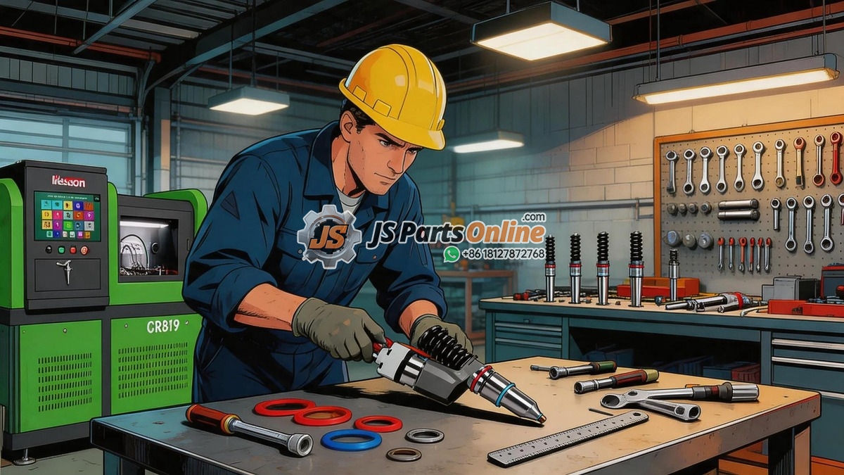
This guide is a comprehensive, step-by-step walkthrough of proper diesel injector installation. Whether you’re a professional technician or an experienced DIY mechanic, following these procedures will ensure your new injectors perform as designed from the first firing stroke.
Before You Start: The Pre-Installation Checklist
Installation errors almost always come from skipping preparation steps. Complete this checklist before you unbox a single injector:
| Check | Why It’s Critical |
|---|---|
| Confirm injector part numbers match the engine | Visually different injectors can share the same mounting dimensions. A C7 injector will physically fit in a C9 engine — but the calibration, flow rate, and nozzle configuration will be wrong |
| Verify IMA/trim codes are available | Without the IMA code, the ECU cannot properly compensate for individual injector flow characteristics. You’ll lose fuel economy, power, and emissions compliance |
| Check the new injector visually | Look for shipping damage: bent solenoid pins, cracked connector housing, damaged nozzle tip (even a tiny impact can distort spray pattern) |
| Verify the seal kit is complete and correct | Missing or wrong O-ring material = immediate leak. Copper washer = one-time use only |
| Confirm you have the right tools | Injector bore brush set, torque wrench (calibrated), non-metallic pick set, borescope, vacuum extractor, assembly lubricant, injector puller (if removing old injectors) |
| Check for technical service bulletins (TSBs) | Many engines have model-specific TSBs about injector installation — updated torque specs, special procedures, known issues with certain production dates |
| Have the ECU diagnostic tool ready | You’ll need it immediately after installation to program IMA codes and clear learned fuel trim values |
Step 1: Removing Old Injectors — Do It Right
If you’re replacing injectors rather than installing new ones into a fresh cylinder head, the removal process sets the stage for everything that follows. A botched removal damages the injector bore — and a damaged bore means the new injector will never seal properly.
Removal Procedure
- Clean everything first. Use degreaser and compressed air to remove all dirt, oil, and debris from the injector area, rocker cover, and surrounding engine surfaces. Any contamination that falls into the open injector hole will sit on top of the piston
- Disconnect fuel lines carefully. Use two wrenches — one to hold the injector inlet fitting, one to turn the line nut. Turning against the injector body can crack internal components
- Remove the hold-down bolt. Some engines use a fork-style clamp, others a direct hold-down bracket. Note the orientation before removal — asymmetrical clamps must go back the same way
- Extract the injector straight up. If it’s carbon-welded into the bore, use a proper hydraulic injector puller. Never pry against the solenoid housing, never hammer on the injector body, and never use a slide hammer attached to the injector
- Immediately cap the injector hole with a clean plug or lint-free rag to prevent debris ingress
If the Injector Is Stuck — The Carbon-Weld Problem
Injectors that have been in service for high mileage often become carbon-welded into the cylinder head. Combustion gases seep past a deteriorating copper washer, carbonize the gap between the injector body and the bore wall, and effectively glue the injector in place. Forcing it out can damage the bore and the injector. The correct approach:
- Apply penetrating oil around the injector body and let it soak — ideally overnight
- Use a hydraulic injector puller that applies even upward force through the injector body clamp groove
- Some shops use an induction heater to thermally expand the cylinder head around the injector — this is effective but requires specialized equipment
- As an absolute last resort, the injector can be drilled and extracted with a puller — this destroys the injector core but saves the cylinder head
Step 2: Cleaning the Injector Bore — The Most Critical Step
This step, more than any other, determines whether your new injector will seal properly and last its full service life. A dirty or damaged injector bore is the #1 cause of repeat copper washer failure and combustion gas blow-by after new injector installation.
Bore Cleaning Procedure
- Insert a bore plug or clean rag below the nozzle seat area to catch falling debris
- Use the correct diameter bore brush for your engine. The brush should fit snugly but not tightly — you’re cleaning, not honing
- Rotate the brush — do not scrub in-and-out. Rotary motion cleans the bore walls; linear motion risks scratching and can push debris deeper
- Clean the nozzle seat with a specialized seat cleaning brush or a lint-free cloth wrapped around a wooden dowel. The seat must be perfectly clean — any carbon residue will prevent the copper washer from seating flat
- Inspect with a borescope. Look for:
- Carbon deposits — if present, clean again
- Pitting or erosion on the seat surface — requires seat resurfacing with a cutter
- Scoring or scratches on the bore walls — may require professional cylinder head machining
- Cracks radiating from the injector bore — rare but catastrophic; cylinder head replacement required
- Vacuum the bore thoroughly using a small-diameter vacuum attachment. Then remove the bore plug/rag
- Final wipe: Use a lint-free cloth lightly moistened with brake cleaner on a clean wooden dowel to wipe the seat surface one final time
Step 3: Preparing the New Injector
Handle new injectors with surgical care. The nozzle tip is precision-machined to micron tolerances — a drop onto a concrete floor can distort the needle seat or damage spray holes.
- Keep the protective cap on the nozzle until the moment of installation
- Inspect all O-ring grooves under a bright light. Any corrosion, pitting, or debris in the groove prevents the O-ring from sealing
- Install the copper washer on the nozzle. One side is typically flat, the other slightly rounded or beveled. Follow the manufacturer’s orientation specification — incorrect orientation is a common cause of immediate fire ring failure
- Install O-rings by rolling them on — never stretch them over the injector body. Use a non-metallic pick to guide the O-ring into its groove
- Lubricate O-rings with clean diesel fuel or dedicated O-ring assembly lubricant. Do not use petroleum jelly (Vaseline) — it’s incompatible with Viton O-rings and diesel fuel
- Apply a thin film of anti-seize compound to the injector body (not the nozzle area) if specified by the manufacturer. This helps with future removal
Step 4: Installing the Injector — Precision Assembly
Insertion
- Remove the protective nozzle cap. Do not touch the nozzle tip with bare hands — skin oils can affect spray pattern during initial operation
- Insert the injector straight into the bore — perfectly vertical. Any tilting can damage O-rings, scratch the bore wall, or bend the nozzle tip against the seat
- Push the injector down by hand until the copper washer contacts the seat. You should feel the washer seat firmly — the injector should not rock or tilt
- If the injector does not slide in smoothly: Stop. Remove it. Check the bore and the injector body for interference. Forcing it will damage O-rings or the nozzle
Hold-Down Clamp Installation
- Position the clamp or fork in the injector body groove. The clamp must sit flat in the groove — not tilted, not partially engaged
- Lubricate the hold-down bolt — threads and underside of bolt head — with the lubricant specified in the service manual. This ensures accurate torque readings by reducing thread friction variation
- If the bolt is torque-to-yield (TTY), use a new bolt. Never reuse TTY bolts — they permanently stretch during initial installation
Torque Procedure
This is where most installation errors occur. Torque is not a target to hit — it’s a specification to follow precisely:
- Initial torque: 50% of specification. Snug all injector hold-down bolts to half torque first, working in the recommended sequence if one is specified
- Second pass: 75% of specification. This ensures even loading
- Final pass: 100% of specification. Use a calibrated digital torque wrench for accuracy
- For TTY bolts: Follow the angle-torque specification exactly. A typical sequence: “Tighten to 25 Nm, then turn 90 degrees, then turn an additional 90 degrees.” Each angle turn must be done in one smooth motion
Common Torque-Related Mistakes
| Mistake | Result |
|---|---|
| Under-torquing | Insufficient clamp load → copper washer doesn’t fully crush → combustion gas blow-by from first startup |
| Over-torquing | Injector body deformation → internal clearances change → solenoid binding, stuck needle, or cracked body |
| Reusing TTY bolt | Bolt has already yielded → cannot achieve proper clamp load at specified torque → seal failure within hours to days |
| Dry bolt threads | Increased thread friction → torque wrench clicks at specified value but actual clamp load is 30-40% low → effectively under-torqued |
| Uneven torque sequence | Injector clamp loads unevenly → copper washer crushes unevenly → leak path on the light-load side |
Step 5: Connecting Fuel Lines and Electrical
- High-pressure line installation: Start all fittings by hand to avoid cross-threading. Use two wrenches for final tightening — one to hold the injector fitting stationary, one on the line nut. Tighten to specification
- Return line connection: Install with a new O-ring or seal. The return line operates at low pressure but any leak introduces air into the system and creates a fire hazard
- Electrical connector: Push the connector onto the solenoid until it clicks. Give it a gentle tug to confirm it’s fully seated. A partially connected solenoid will either not fire or fire intermittently — and intermittent firing often damages the injector and the ECU driver circuit
- Wire routing: Secure the injector wiring harness away from hot surfaces (exhaust manifold, turbocharger) and moving parts (fan belt, cooling fan). Use the factory harness routing clips
Step 6: Post-Installation — Before You Start the Engine
IMA Code Programming
If the new injector has an IMA (Injector Menge Abgleich) or trim code, you must program it into the ECU before starting the engine. The ECU uses this code to adjust injection pulse width for each cylinder, compensating for individual injector flow characteristics. Without IMA coding:
- Fuel delivery can be off by 5-15% per cylinder
- Cylinder-to-cylinder balance is compromised — rough idle, vibration
- Fuel economy suffers — the ECU enriches all cylinders to compensate for the leanest one
- DPF regeneration frequency increases due to imbalanced combustion
Use your diagnostic tool (Bosch KTS, Delphi DS, Snap-on, Autel, etc.) to enter the IMA code for each injector in the correct cylinder position. Double-check every digit — entering a wrong code is worse than entering no code at all.
Priming the Fuel System
If the fuel system was opened during installation, it must be purged of air. Crank the engine with the injector electrical connectors disconnected (or use the diagnostic tool’s “fuel system prime” function) to circulate fuel through the rail and return lines. Connect the injectors and attempt startup only after the fuel system is fully primed. Air in a common rail system can cause injector cavitation damage.
First Start Procedure
- Start the engine and let it idle — do not rev immediately
- Listen for unusual noises: ticking (injector firing should be barely audible), chuffing (gas blow-by at the copper washer), knocking (incorrect injection timing)
- Watch for fuel leaks at all connections — use a bright flashlight
- Spray soapy water around each injector base — no bubbles should appear
- Monitor live data on your diagnostic tool: rail pressure stability, injection quantity deviation, cylinder balance values
- Let the engine reach full operating temperature and re-inspect everything
Recommended Torque Specifications (Reference Only — Always Consult Your Service Manual)
| Engine Family | Injector Hold-Down Bolt | High-Pressure Line Nut |
|---|---|---|
| Caterpillar C7/C9 (HEUI) | 35-40 Nm + 90° (if TTY) | 40 Nm |
| Caterpillar C13/C15 | 45-50 Nm | 45-50 Nm |
| Cummins ISB 6.7L | 13-15 Nm (rocker lever style) | 30 Nm |
| Cummins ISX15 | 45-50 Nm (clamp style) | 45 Nm |
| Detroit Diesel DD15 | 30-35 Nm | 40 Nm |
| Bosch common rail (generic) | 25-30 Nm | 25-35 Nm |
Disclaimer: These values are for general reference. Always verify against the specific engine’s factory service manual. Torque specifications can change between engine generations and production years.
Post-Installation: First Service Check
After 50-100 miles (or 1-2 operating hours for stationary engines), perform a follow-up inspection:
- Re-torque hold-down bolts if the manufacturer specifies a hot re-torque procedure
- Inspect all fuel connections for weeping or wetness
- Check the injector area for any carbon tracking (black, sooty deposits) around the injector base
- Run a cylinder balance test with your diagnostic tool to confirm even fuel delivery
- Check ECU fault codes — look for injector circuit faults, fuel pressure deviation, or cylinder imbalance codes
Quality Injectors for a Professional Installation
At JS Parts Online, our diesel injectors are pre-assembled with OEM-quality seal kits, tested and calibrated, and shipped with complete IMA code documentation — everything you need for a successful installation:
- Caterpillar Fuel Injectors — Ready to install with complete seal kits
- Bosch Common Rail Injectors — IMA codes included for immediate ECU programming
- Denso Diesel Injectors — Precision-calibrated for Japanese diesel engines
- Fuel Injection Pump Plungers — Complete your fuel system rebuild
Conclusion
Installing diesel injectors correctly is not complicated — but it is unforgiving. Every step matters: the bore cleaning, the torque sequence, the IMA code entry, the first-start inspection. Skip one step and you’ll be back in the engine bay in a week, pulling out a failed injector and wondering what went wrong.
The difference between an injector that lasts 3,000 miles and one that lasts 300,000 miles is often not the injector itself — it’s the installation. Take your time, follow the procedures, use the right tools, and verify every step. Your engine will thank you with years of smooth, efficient operation.





JSPartsonline:
Focus on injectors for 12 years,We sell high-quality fuel injectors at competitive prices.
Copyright 2025 © YUN·X . All right reserved.
